Dust becomes a real issue once dry OCC moves through shredding, conveying, separation, and fiber opening. Paper fines, coating debris, dirt, and other small contaminants can be released at every drop, impact, or high-energy opening point. The dust system therefore needs to be considered as part of the process itself. If it is added too late, the plant may remain dusty or the airflow may start carrying useful light fiber out with the waste.
A better approach is to engineer the dust system as part of the material flow. The design starts with release points. It then connects hood geometry, enclosure, branch airflow, duct losses, filtration, fan pressure, maintenance access and safety controls into one operating boundary. OSHA lists combustible dust among the hazards relevant to paper recycling, while its current combustible-dust National Emphasis Program explicitly includes paper dust and paper recycling operations.[1][2]
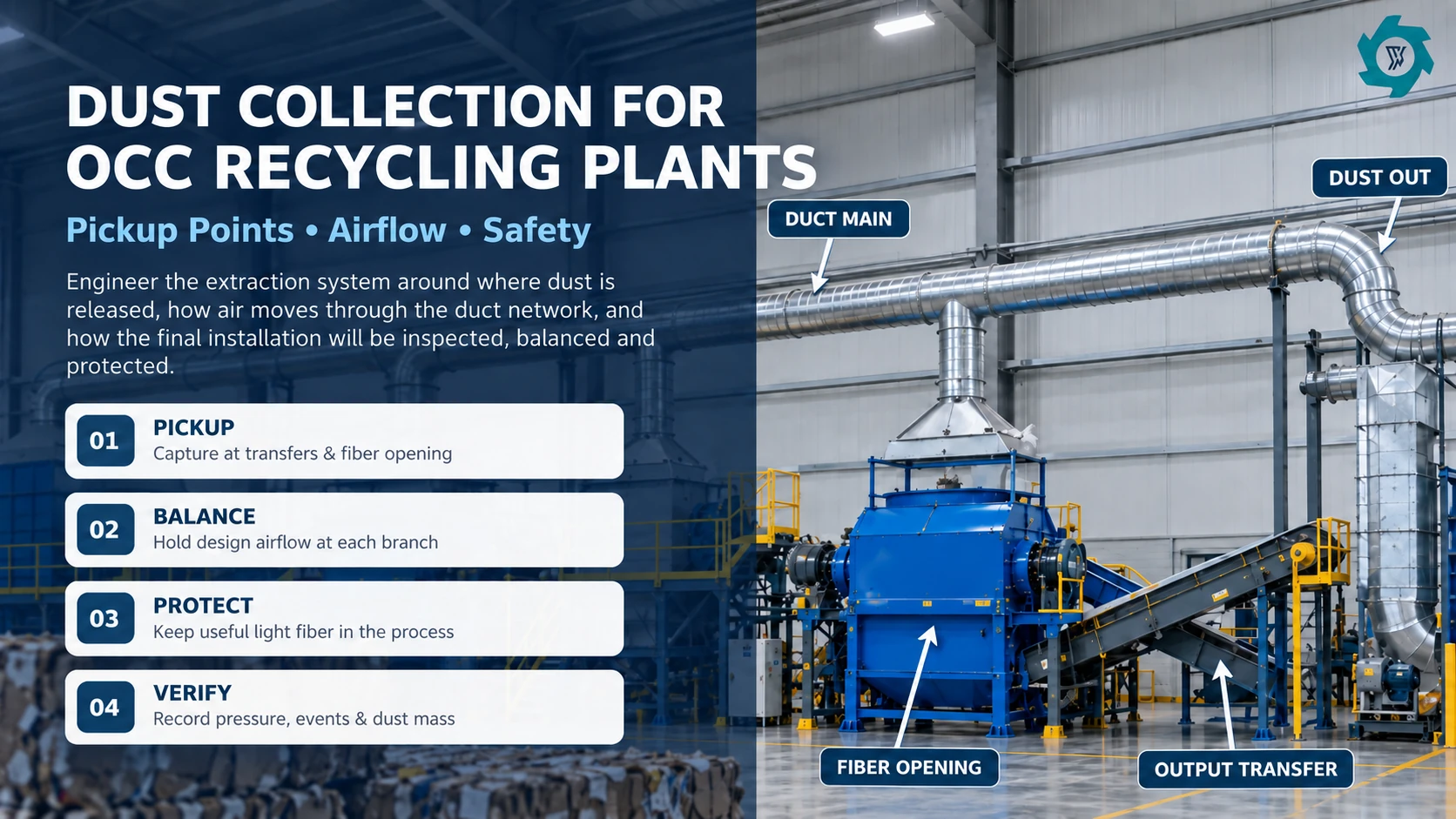
Dust collection should follow the OCC process, not the building volume
An OCC recycling plant uses a dry mechanical process that can include feeding, shredding, magnetic separation, dry fiber opening, dust collection, fiber handling and baling. That process boundary matters because dust generation is concentrated. A bale staging area may look dirty but release little airborne material during normal storage, while a compact transfer chute can create a strong local plume every time shredded cardboard falls through it.
For an OCC recycling plant, effective dust control depends on three practical decisions: where dust is released, how each pickup point is connected to the airflow system, and how the completed system will be tested before acceptance. They influence how well dust is captured, how much fiber is lost, how clean the plant stays, and how reliably and safely the equipment runs.
Start by following the material through the line and noting where its speed, direction, height, or form changes. Open drops, impact points, screens and fiber-opening machines deserve attention. The goal is not to connect every machine to one large duct. The goal is to contain the releases that would otherwise become fugitive dust.
| Process location | Why dust can be released | Useful first design move |
|---|---|---|
| Shredder discharge | Torn board falls from an enclosed chamber into a conveyor or chute | Enclose the discharge transition and capture across the opening rather than from far above it |
| Transfer point | Material drops, changes direction and displaces air | Reduce free-fall height, close unused openings and place extraction near the dust path |
| Magnet or inspection transfer | Opened material can be spread into a thin burden with exposed fines | Keep access practical; avoid a hood that interferes with metal removal or inspection |
| Dry fiber opener | Mechanical action separates corrugated structure and creates light fines | Use close enclosure with deliberate inlet air and service doors that do not defeat capture |
| Screen/classifier, if used | Vibration and air movement can release a fine fraction | Connect the enclosure to the dust system while preserving the intended separation function |
| Final transfer or baler feed | Loose fiber can fluff when it changes direction or is compressed | Capture fines without turning the hood into a product-removal device |
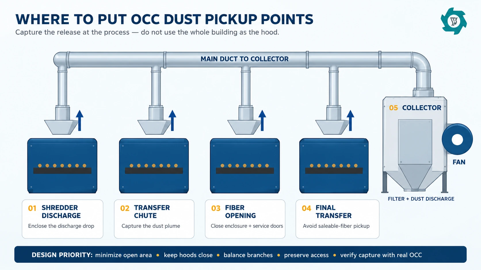
Put the hood close to the source before increasing airflow
Local exhaust ventilation works by capturing a contaminant near where it is generated. NIOSH describes engineering controls such as local exhaust ventilation as a way to remove airborne emissions at the source, and its research repeatedly shows that enclosure, hood design and capture airflow are interdependent.[3] In an OCC line, better enclosure can reduce the volume of useful light fiber that the extraction system sees.
A hood mounted far above an open conveyor has to influence a large volume of room air before it can influence the dust plume. Cross-drafts from doors, fans, forklifts or makeup air can overpower that weak capture zone. Moving the hood closer, adding side panels or enclosing the transfer narrows the airflow path. The same control objective may then be achieved with less total air.
Do not confuse face velocity with capture velocity. A technician can measure a fast air speed at a small duct opening while dust still escapes a transfer point half a meter away. The relevant question is whether the air movement at the release zone consistently carries the dust into the hood under normal loading. NIOSH field work uses smoke or tracer methods alongside velocity measurements because the direction and stability of airflow matter, especially where cross-drafts are present.[4]
Access is part of hood design. Operators still need to inspect belts, clear material after lockout, replace wear parts and open service doors. If maintenance requires removing the hood, production teams may leave it off. A useful quotation should therefore show the hood, access doors, flexible connections where needed and the intended cleaning route.
Airflow must capture dust without turning good fiber into reject
OCC is not mineral dust. The process contains very light pieces of saleable paper fiber. An aggressive pickup at the wrong point can improve the appearance of the machine while increasing dust-bin mass and decreasing accepted output. NIOSH guidance on local exhaust ventilation also shows that transport-system design can affect product recovery, which is one reason airflow should be matched to the material and process rather than simply maximized.[5]
For buyers, the useful metric is not only collector airflow. Track what happens to material. During trials, weigh the dust/fines stream separately and compare it with accepted output. If a damper adjustment sharply increases collected mass without improving visible capture or housekeeping, the system may be extracting product rather than solving a dust problem.
This is also why a single generic “capture velocity for paper” should not be copied into the RFQ as a guarantee. Required airflow depends on hood type, enclosure, dust release energy, opening size, cross-drafts and process geometry. Use published ventilation values only as design references for similar operations, then verify the actual OCC installation. The engineering sequence is: define the source and hood, estimate containment flow, calculate pressure loss, select the fan, balance the branches, and confirm performance while real material is running.
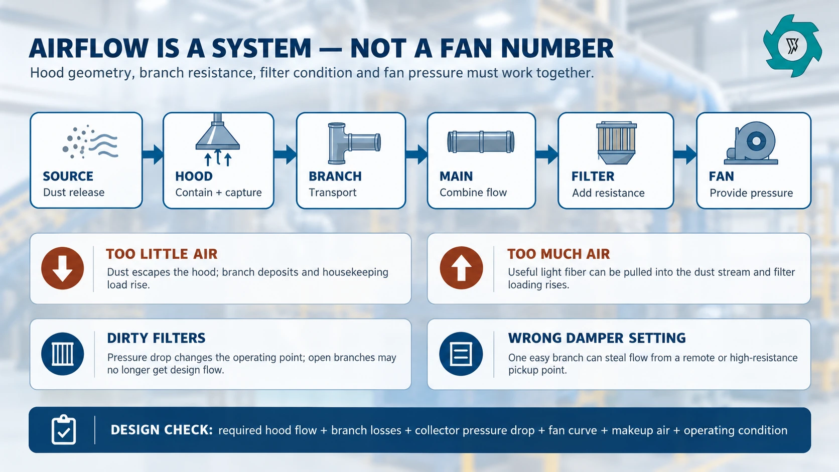
Design the branch ducts and main duct as a pressure network
Once each pickup has an airflow requirement, the duct network has to deliver it at the same time. A short branch near the fan does not experience the same resistance as a long branch with multiple elbows. With both dampers wide open, the shorter branch may pull too much air, leaving the farther pickup with insufficient suction.
Every bend, branch, damper, separator, and filter adds resistance to the duct system. Problems often appear when ductwork is routed late in the layout, after conveyors, cable trays, and fire-protection lines are already fixed, forcing extra turns that increase pressure loss.
Transport also matters inside the duct. The air has to keep the intended dust fraction moving without creating avoidable deposits. But transport velocity should not be treated as a universal number independent of particle properties and duct arrangement. NIOSH notes that conventional high-velocity and engineered low-velocity systems can follow different transport strategies while still maintaining capture at the hood; the system concept has to match the material and geometry.[5]
For an OCC buyer, ask the supplier to mark branch sizes, main-duct sizes, dampers and access/cleanout points on the drawing. Also ask what happens when one process machine is idle. Closing an idle branch can improve available flow elsewhere, but only if the control logic and balancing method anticipate that operating state. Random damper changes by operators are not a substitute for a commissioned system.
The collector and fan are only useful at the required operating point
A fan catalogue can show impressive free-air volume, yet free-air volume is not the installed airflow. The fan must overcome the resistance of the complete network at the design flow. Filter pressure drop is especially important because it changes as the elements load and are cleaned. If the selection barely meets the requirement with a new filter, the farthest pickup may become ineffective as differential pressure rises.
Specify how filter condition will be observed. Differential-pressure indication is more useful than waiting for visible dust escape. Trend it during commissioning and normal operation. A sudden change can indicate filter loading, cleaning problems, leakage, an open access door or another change in system resistance.
The OCC recycling equipment guide already treats dust handling as part of complete-line capacity. This article adds the reason: a plugged collector, a poorly balanced branch or frequent filter maintenance can become the practical bottleneck even when the shredder and fiber opener are mechanically capable of the target throughput.
If the broader project handles paper grades beyond OCC, compare the dust duty against the actual feed described for the waste paper cellulose recycling line. Fine office paper, coated trim, corrugated bales and mixed paper can produce different airborne loads.
Makeup air must be considered with the exhaust system
Every cubic meter of air removed by the dust system has to be replaced from somewhere. If the building cannot supply enough makeup air, the workshop can operate under excessive negative pressure. Air then enters through doors, wall openings and other uncontrolled paths. Those cross-drafts may interfere with the pickup points that were carefully balanced during commissioning.
This effect is easy to miss when the dust collector is tested by itself. A hood may capture well while nearby doors are closed, then lose control after loading doors open or another exhaust system starts. For that reason, commissioning should record the normal building condition as well as the fan and damper settings. Large doors, roof fans, process exhausts and planned makeup-air units should be operated in the same state expected during production.
Makeup air should also be introduced without blowing directly across a dust-release point. A strong supply-air jet near an open transfer can push the plume away from the hood even when the measured duct airflow has not changed. The location and direction of replacement air therefore belong in the same review as hood position, enclosure openings and local cross-drafts.
Returning filtered collector air to the building should not be treated as a simple energy-saving decision. The arrangement depends on the dust characteristics, filtration performance, combustible-dust review and local requirements. Where return air is proposed, the supplier and site engineer should state the filtration basis, monitoring method, abnormal-condition response and approval responsibility. Where air is exhausted outdoors, the project should account for the corresponding replacement-air load and its effect on heating, cooling and building pressure.
For the buyer, the practical requirement is straightforward: define the expected exhaust volume together with the makeup-air strategy before the plant layout is frozen. During commissioning, verify capture with the workshop operating in a realistic condition rather than with doors, fans and adjacent systems arranged only to make the dust test easier.
Separate dust collection from light-reject separation
These two functions use air, but they are not the same job. A light-reject separator intentionally changes the material split by removing selected film, labels or other light contaminants. A dust collector should capture airborne fines and keep them out of the workplace and air system. Combining the labels on a flow diagram can hide the mass balance: the buyer no longer knows whether collected material is process reject, useful fiber, or housekeeping dust.
Keep the streams visible. If the line has a light-reject stage, identify its product and reject streams separately from the dust/fines stream. Weigh them separately during acceptance. This is particularly important when the final dry product is sold by mass, because an air system that quietly removes a large fiber fraction can make a visually clean plant while weakening yield.
Combustible-dust safety requires a project-specific review
Paper dust can be combustible. OSHA’s revised 2023 National Emphasis Program lists paper among combustible organic dusts and includes paper products and paper recycling operations within the program scope.[2] OSHA’s combustible-dust guidance also highlights the risk created when combustible dust, an ignition source, oxygen, dispersion and confinement occur together, and it points to controls such as preventing leaks, housekeeping, grounding/bonding and appropriate explosion protection for dust-handling systems.[6]
That does not mean every OCC collector needs the same hardware. The actual dust should be characterized, and the final design should be reviewed by qualified combustible-dust and fire-protection specialists under the rules that apply at the site. NFPA 660:2025 brings the main combustible-dust requirements together in one standard. OSHA guidance also refers to controls such as venting, suppression, and isolation for deflagration hazards.[7][8]
The supplier and site engineer should agree on the basis for combustible-dust protection before the system is finalized. That includes the dust characteristics, collector location, explosion protection and isolation approach, ignition control, grounding, electrical classification where needed, return-air arrangements, and who is responsible for local approval. The authority having jurisdiction, insurer and local codes can change the final arrangement.
Collector location is a layout decision for the same reason. Service doors, dust discharge, explosion-relief zones if used, clean-air exhaust, makeup air, pedestrian routes and fire access all need physical space. A collector placed in the last empty corner can create a costly redesign after the process line is already anchored.
Housekeeping is a diagnostic signal, not the primary capture method
Good housekeeping still matters, but recurring deposits often tell you where the extraction system is weak. Map where fines accumulate after a full shift. Repeated dust beneath one transfer may indicate an open gap or spill problem. Dust on an elevated beam near a fiber opener can suggest airborne escape. Deposits around a collector flange can indicate leakage.
Avoid cleaning practices that simply re-suspend dust. OSHA guidance warns against allowing deposits to accumulate and against dispersing dust into the air with compressed air.[6] The plant’s cleaning method should be selected through the same hazard review that covers electrical classification and combustible-dust housekeeping.
Maintenance teams should also inspect flex connections, access-door seals, duct supports, elbows, dampers and filter-cleaning equipment. A damaged duct or open cleanout changes system resistance and can rob flow from other branches. Keep a baseline set of pressure and airflow readings from commissioning so troubleshooting starts with evidence.
Commission the dust system while the OCC line is actually processing material
A no-load fan test confirms rotation and basic controls. It does not prove dust capture under production conditions. The acceptance run should use representative material and deliberately include difficult-but-normal feed inside the agreed boundary. Very dry corrugated, compacted sections, normal tape and a realistic fraction of fines may load the air system differently from a clean demonstration sample.
Record both running time and elapsed time. Log stops, reversals, operator interventions, manual clearing, downstream holds and maintenance stops. These events matter because an air system may look stable during a short continuous run but become troublesome when doors are opened, a branch is isolated or filters load over a full cycle.
At agreed pickup points, record the commissioning evidence selected by the ventilation engineer: airflow or velocity readings, damper positions, fan condition, differential pressure and visual smoke/tracer observations where appropriate. Repeat critical readings with a reasonably loaded filter condition rather than relying only on brand-new elements. Inspect the work area for leakage and settled dust after the run.
Then close the material balance. Weigh accepted input, accepted output, ferrous output, other rejects, oversize/return if present, dust/fines, retained material and the unexplained difference as separate entries. Do not merge retained material and unexplained difference. Report both accepted-input rate and accepted-output rate on the defined time basis. If the dust system includes downstream collected product that will be sold or returned to the process, sample and weigh it as its own stream.
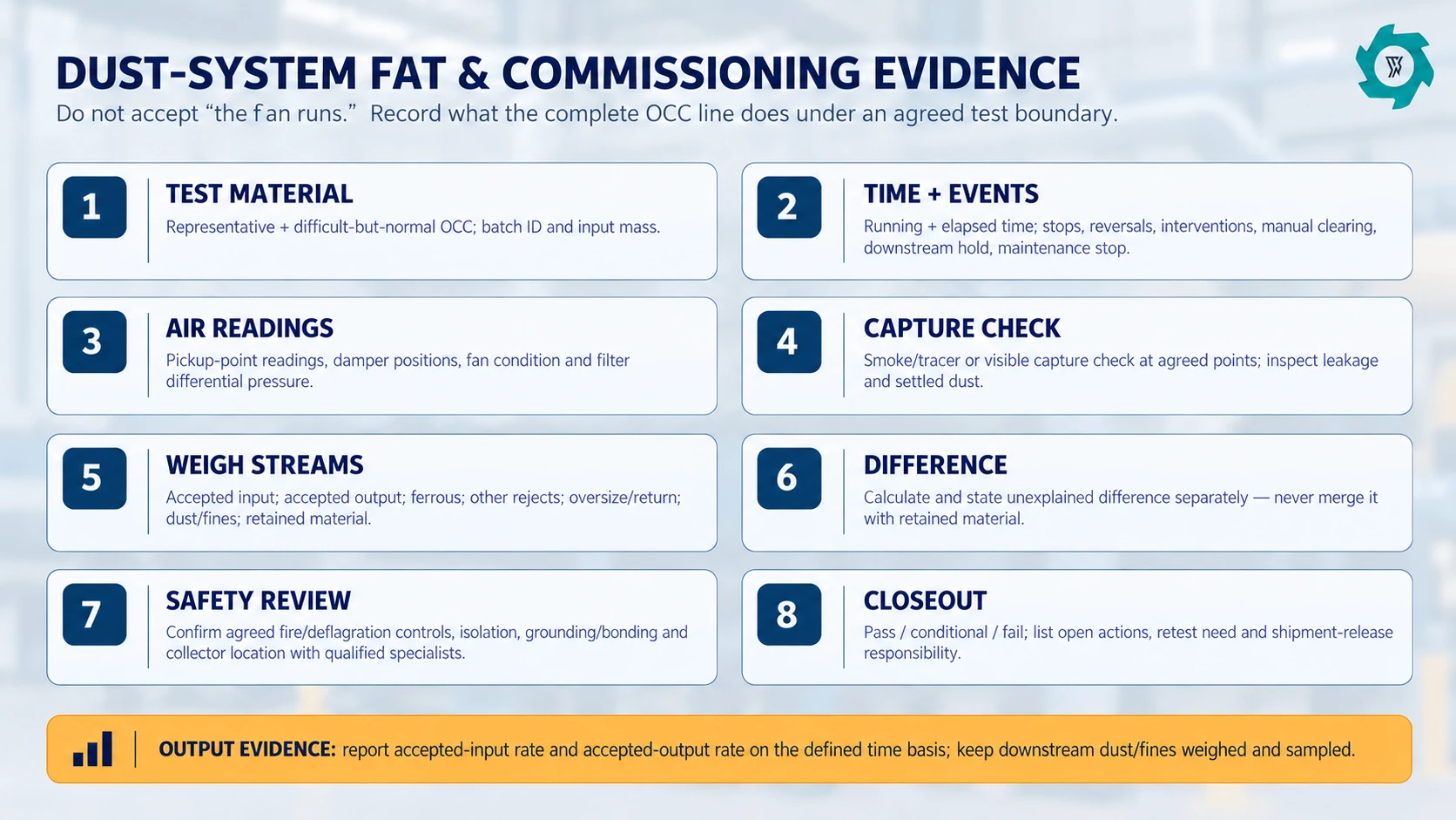
What to put in an OCC dust-collection RFQ
Start with the actual material and process. Include photos or video of the regular feed, the driest expected condition, throughput, hours per shift, the process flow and which machines are included. If a double shaft shredder is used for primary size reduction, give the real discharge arrangement because the dust pickup is defined by the interface.
Then require the proposal to state what is included: pickup hoods or enclosures, branch ducts, main duct, dampers, cleanouts, flexible connections, separator/cyclone if used, filter collector, fan, discharge device, supports, instrumentation, controls, electrical scope and installation boundary. Ask for the design airflow at each pickup and the corresponding system pressure basis. If the supplier excludes duct installation, structural supports, fire/deflagration protection or makeup air, those exclusions should be written clearly.
Define the evidence needed before shipment or site sign-off. A strong acceptance package includes drawings, fan data, filter data, instrument list, damper schedule, operating sequence, inspection points, maintenance instructions and the agreed test sheet. It should also identify which items cannot be finalized until site dust testing, local code review or authority approval.
RFQ data package:
- Representative OCC photos/video, moisture range and difficult-but-normal material.
- Sustained complete-line throughput and operating hours.
- Process layout with all dusty transfers and enclosure openings.
- Required pickup points and any branches that operate intermittently.
- Accepted-output definition and allowable product loss to dust/fines.
- Collector location constraints, duct route, clear height and service access.
- Site voltage, controls integration, alarm/interlock expectations and instrument list.
- Combustible-dust/fire design responsibility, local code basis and approval boundary.
- Commissioning readings, material mass balance and FAT closeout format.
Use the dust system to support stable production, not just a clean photograph
The most effective OCC dust system is rarely the one with the largest fan or the most pickup branches. It is the one that contains the real release points with practical enclosures, moves enough air through a balanced network, maintains that performance as filters load, and does not carry excessive saleable fiber into the dust stream.
For a new line, freeze the dust concept while there is still time to change transfer heights, service doors and collector location. For an existing line, start with a dust map and baseline measurements before replacing equipment. In both cases, connect air-system evidence to the material balance and operating-event log. That turns dust collection from a vague environmental accessory into an engineered production system that can be specified, tested and maintained.
Frequently asked questions
Where should dust pickup points be placed in an OCC recycling plant?
Start where dust is actually released: shredder discharge, open transfer drops, dry fiber-opening equipment, screens or classifiers when used, and dusty final transfers. The hood should be close enough to contain the release without obstructing material flow, inspection or maintenance.
How do you size airflow for OCC dust collection?
Do not size the system from one generic capture-velocity number. Define each hood and enclosure, estimate the airflow needed for containment, calculate branch and main-duct losses, add collector pressure drop, then select the fan from the full system operating point. Final settings should be balanced and verified during commissioning.
Can too much extraction remove useful cardboard fiber?
OCC contains light, saleable fiber that can be entrained if a pickup point is too open or the local air velocity is excessive. Better enclosure usually reduces the airflow needed for control. Dust and recovered fiber should be weighed separately during trials so the plant can distinguish cleaner air from unnecessary product loss.
What should be checked during OCC dust-system FAT or commissioning?
Use representative OCC and a defined operating boundary. Record running and elapsed time, operating events, pickup-point airflow evidence, fan and damper settings, filter differential pressure, visible capture or tracer results, leakage, dust accumulation, and separately weighed material streams including dust and fines. State any unexplained mass difference separately.
Need an OCC Dust-Control Layout Review?
Send your material photos, line flow, target throughput, workshop drawing and the dusty points you are trying to control. YUXI can review the mechanical interfaces and prepare a preliminary dust-collection scope for supplier and site-engineer coordination.
Sources
- OSHA — Paper Recycling hazards.
- OSHA — Combustible Dust NEP (2023).
- NIOSH — Engineering Controls overview.
- NIOSH — Report 322-12a; airflow testing.
- NIOSH — Exhaust Ventilation; duct design.
- OSHA — Dust Guidance; prevention measures.
- NFPA — 660:2025 combustible-dust standard.
- OSHA — Technical Manual; dust protection.