Automation Should Stabilize the Material Flow, Not Just Start Motors
Material moves through the OCC line as one connected flow, even though it passes through several different machines. A problem at one point can quickly change the load somewhere else. The controls need to follow those changes across the line, not just watch whether each motor is still running. A drive may show no fault while feeding is already becoming unstable, so early changes in flow and load are often more useful than waiting for a shutdown alarm.
For a buyer, the useful question is not “Does the line have a PLC?” Nearly every modern line can be supplied with one. The better questions are: what conditions must be true before each machine can run, which upstream machines slow or stop after a downstream fault, what signals regulate the feed rate, what the operator sees first when a trip occurs, and what must be reset before production restarts. Moving machinery and unexpected startup are recognized hazards in paper recovery work, so these control decisions belong in the design review rather than being left to commissioning.[1]
Automation cannot make wet, springy, wire-rich bales behave like clean loose sheets, and it cannot create capacity where a transfer chute or downstream machine is physically undersized. For the equipment sequence and process boundary, use the OCC recycling plant page as the starting reference. The control system should then be designed around the real feed, actual buffers, installed machine response and operator tasks.
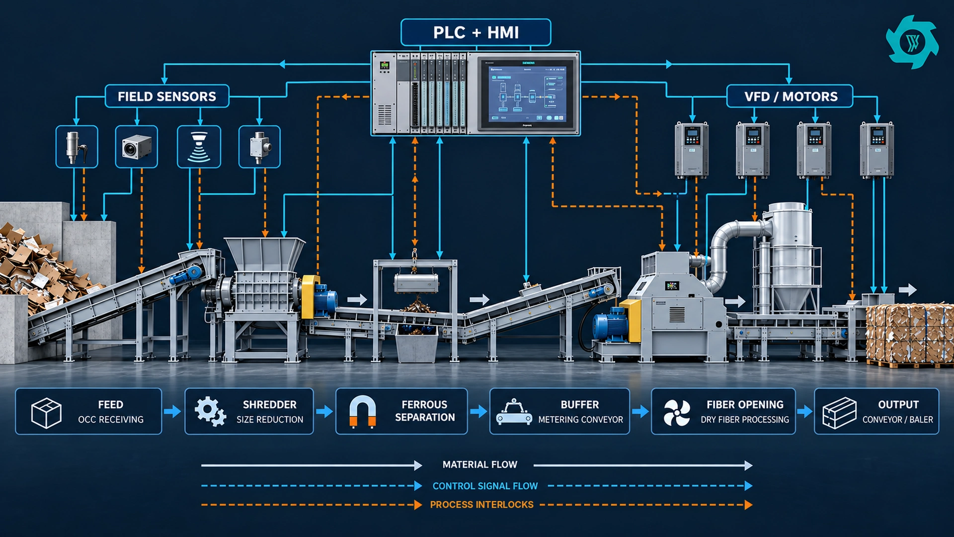
Start With a Control Architecture That Matches the Physical Line
At field level are sensors, switches, encoders, motor feedbacks and safety devices. The control layer contains the PLC or distributed controllers that evaluate permissives, sequence commands and process interlocks. The actuation layer contains motor starters, variable-frequency drives, valves, gates and other devices that change the process. The HMI or supervisory layer gives operators status, alarms, trends, setpoints and recovery instructions.
The electrical design for industrial machinery normally sits inside a wider machine-safety and electrical framework. The electrical design should cover electrical, electronic and programmable electronic equipment on individual machines and coordinated groups of machines.[2] Machinery risk assessment and risk reduction should follow a systematic method across the machine life cycle.[3] These references do not turn one generic PLC program into a compliant plant. They are better used to frame the design review: identify hazards and operating states first, then decide which functions belong in normal process logic and which are safety-related.
Do Not Treat Permissives, Process Interlocks and Safety Functions as the Same Thing
A permissive is a condition that must be true before an action is allowed. A process interlock protects equipment or material flow by changing operation when a process condition becomes unacceptable. A safety function reduces a defined risk and must be designed and validated to the required performance for that risk. Safety-related parts of the control system require a defined design and integration process for the safety functions they perform.[4]
For example, “downstream conveyor running” can be a normal permissive for the upstream feeder. A high-high buffer level can be a process interlock that stops upstream feed before material spills or packs into a transfer. A guard-door device, emergency-stop function or other risk-reduction function belongs in the safety analysis; it should not be described casually as another PLC bit. The emergency-stop function needs its own design principles and should be distinguished from other functions such as reversal or motion limitation.[5]
That distinction matters during troubleshooting. If an operator sees “feed conveyor stopped,” the HMI should make it clear whether the machine is waiting for a normal process permissive, has been stopped by a process fault, or is inhibited by the safety system. One message that simply says “interlock active” forces maintenance to investigate several completely different situations.
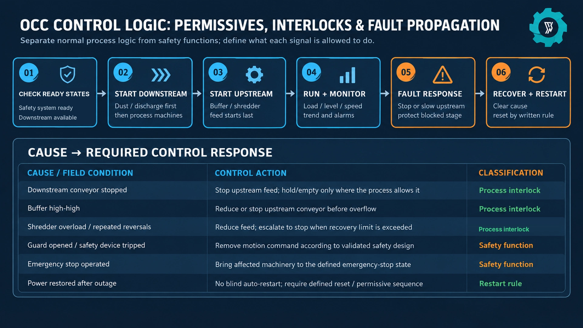
Sequence the Line From the Discharge End Back Toward the Feed
For many continuous material-handling lines, start-up is most robust when discharge paths and supporting systems are proven ready before upstream material is released. The exact order depends on the installed process, but the logic is easy to test: a machine should not be allowed to feed into a stage that cannot receive its material.
A typical sequence may prove the dust system and discharge section available, start downstream conveyors and process machines, establish buffer or transfer readiness, and only then enable the primary feed. Shutdown normally reverses the material logic: stop new feed first, allow defined sections to clear when appropriate, then stop downstream equipment in a controlled order. A hard emergency event is different; it follows the defined emergency response rather than a production-emptying sequence.
Build Feed Control Around Load, Level and Downstream Status
Feed control is where plant automation can have the most visible effect on daily stability. OCC arrives as a low-density, springy and sometimes compressed material. Even when the average mass rate is reasonable, short slugs can push the shredder or fiber-opening stage beyond its comfortable operating window. Running the infeed conveyor at one fixed speed makes that variability the downstream machine’s problem.
A better arrangement uses a variable-speed feeder or conveyor and adjusts it from more than one signal. Useful inputs can include buffer level, shredder motor load or current, shredder reversal frequency, downstream-ready status, conveyor motion, and high-level switches. The exact control method depends on how quickly the process responds. A heavily damped buffer can use slower corrections; a direct feed into a shredder may need tighter load-based limits.
For projects receiving both loose cardboard and compressed bales, the control settings should reflect the different release behavior. The physical differences are covered in Loose Cardboard vs Baled OCC: How Feed Form Changes Plant Design. In the PLC, that difference may justify separate recipes or parameter sets for feed acceleration, normal speed band, high-load response and buffer limits. A recipe should change only the parameters that have been validated for that feed state; it should not silently bypass protection or safety functions.
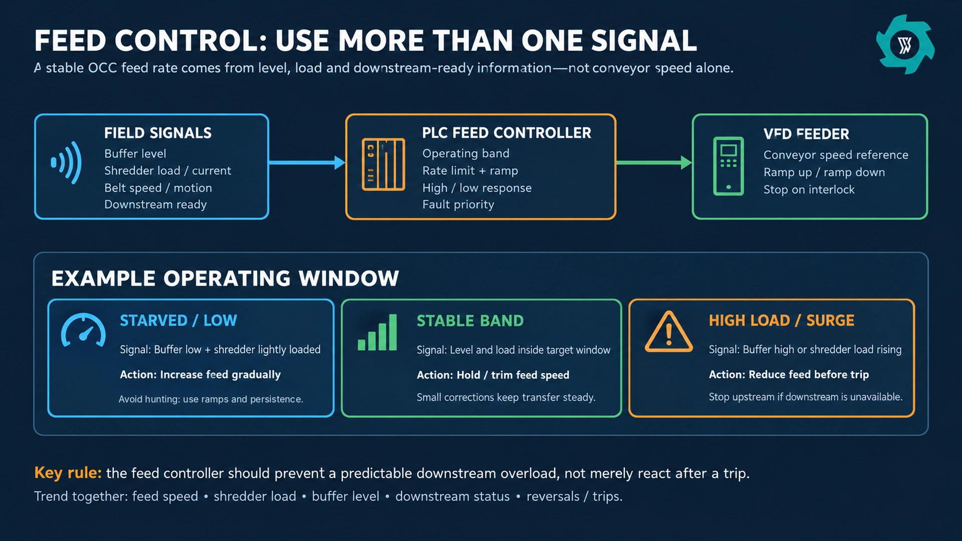
Use Deadbands, Ramps and Persistence So the Controller Does Not Hunt
A feed loop that reacts to every small signal change can make the line less stable. Suppose shredder current crosses a high threshold for half a second whenever a thick fold enters. If the conveyor immediately drops from full speed to zero and then jumps back to full speed, the line will cycle between starvation and surge. The operator may see more trips even though the controller is “active.”
Three simple tools help. First, use an operating band rather than one exact target. Second, ramp speed changes so the material bed changes progressively. Third, add persistence or filtering where justified so a brief transient does not receive the same response as a sustained overload. The response should still be fast enough to protect the process. That balance is established from machine behavior and test data.
Make Downstream Fault Propagation Explicit
One of the most important automation questions is what happens after a downstream trip. If the fiber-opening machine stops but the shredder and feed conveyor continue running, material can fill the transfer, pack the buffer, bury a sensor and create a manual clearing job. The original electrical fault may take seconds to reset; the material accumulation can take much longer to remove.
The cause-and-effect matrix should therefore show fault propagation. It does not need to stop every machine for every event. A buffer with sufficient available capacity may allow the upstream section to finish a short, defined transfer. A baler stop may be absorbed by a discharge bin with adequate capacity. A dust-system problem may require stopping only the generating equipment connected to the affected extraction zone. The design goal is controlled containment, not maximum shutdown.
When a condition is allowed to run through a buffer, state the buffer assumption. Record usable volume, high and high-high level points, normal residence time, and the rate at which the downstream stage can recover.
Design the HMI Around Decisions the Operator Actually Has to Make
A useful HMI does more than draw colored motors on a process diagram. During a disturbance, the operator needs the first cause, the equipment affected, the current state, and the permitted next action. A screen that fills with secondary alarms can hide the initiating event. If one downstream trip creates 20 upstream “not running” alarms, the first-out condition should still remain visible.
Alarm messages should be specific enough to act on. “Conveyor 3 fault” is weaker than “C3 motion not proven after start command.” “Interlock active” is weaker than “B2 high-high level: upstream feed inhibited.” Where the hardware supports it, trend screens should align feed speed, motor load, level, reversals, stops and downstream-ready signals on the same time axis. That turns a recurring instability into evidence instead of a shift-by-shift argument.
Plan Manual and Recovery Modes Before the First Jam
Automatic mode is only one plant state. Commissioning, inspection, cleaning and recovery require other modes, and those modes need rules. Manual mode may allow an individual conveyor to operate independently of selected normal process permissives, but the applicable safety-related functions must remain governed by the safety design. The permitted conditions and operating limits should therefore be defined before commissioning.
Write down what “manual,” “jog,” “local” and “maintenance” mean for each machine. State which normal process interlocks remain active, which conditions may be overridden, how an override is authorized, how long it can remain active, and how the HMI displays it.
Servicing and unjamming also sit outside ordinary production logic. Servicing and maintenance tasks that expose employees to unexpected energization, startup or release of stored energy require an energy-control program and documented hazardous-energy control procedures.[6] A PLC “stop” command or an HMI maintenance page is not, by itself, an energy-isolation procedure.
Define Restart Behavior After Faults, Power Loss and Emergency Stops
Restart logic deserves its own review because it is easy to overlook when the plant is running normally. Ask what happens after a brief power interruption. Ask whether a field device that returns to “ready” can cause automatic restart. Ask which trips require a manual reset and whether that reset occurs at the affected machine or a central station. Then test the answers.
For process faults, the most useful rule is usually that the original cause must be cleared before the restart path becomes available. For example, a high-high buffer trip should not disappear simply because an operator acknowledges the alarm. The level must return to the reset band, downstream equipment must be available, and the defined sequence must be re-established. This prevents a quick reset from feeding the same blocked condition again.
Guarding and access remain part of the physical risk-control system. Machine guarding should protect workers from hazards such as ingoing nip points, rotating parts and flying material.[7] The control system should support the guarding concept rather than becoming the reason a guard is routinely defeated for production convenience.
Instrument the Conditions That Change Operator Decisions
More sensors are not automatically better. Every device adds installation, cleaning, calibration and diagnostic work. Instrumentation is valuable when a signal changes a control decision, provides evidence for a recurring fault, or confirms that a commanded action really happened.
Useful examples in an OCC line include level switches or continuous level devices at buffers, belt-motion or zero-speed detection on critical conveyors, VFD current or torque feedback where it meaningfully represents load, rotation feedback on driven equipment, differential pressure or airflow evidence where the dust system requires it, bin-full status at reject or dust discharge points, and position feedback on gates that can block material flow.
Integrate Dust-System Status Without Repeating the Dust-System Design
Dry OCC shredding and opening can generate paper fines, so dust equipment often has operating dependencies with the process. Combustible dust is a recognized hazard in paper-recycling operations.[1] The control question is therefore not only whether the collector has a start button. It is what process is allowed to run when required extraction is unavailable, which status proves availability, and how a collector or discharge fault propagates.
The physical pickup points, airflow and duct design are a separate engineering job; see Dust Collection for OCC Recycling Plants: Pickup Points, Airflow & Safety for that boundary. In the PLC narrative, keep only the dependencies: fan or airflow status, collector fault, hopper or rotary-valve status, affected process zones, alarm priority and restart condition.
Require a Cause-and-Effect Matrix, I/O List and Alarm Philosophy
A quotation that says “PLC automatic control included” is too thin for a connected plant. The buyer should be able to review the control intent before the software is hidden inside a finished cabinet.
The I/O list identifies each field signal, tag, type and purpose. The cause-and-effect matrix states what the system does when important conditions occur. The alarm philosophy or alarm list defines priority, message wording, acknowledgement, latching and reset behavior. Add a sequence narrative for start, stop, fault recovery and mode changes. Together, these documents let operations, electrical and mechanical teams review the same behavior before commissioning.
Where controls cross package boundaries, add an interface register. An owner-supplied baler, site dust collector or upstream conveyor needs named signals and responsibilities. The broader commercial and interface structure is covered in the OCC Recycling Plant RFQ Checklist. For automation, the important addition is to define direction, electrical form, fail state and meaning of every exchanged signal.
Test the Automation With Abnormal Events, Not Only a Successful Auto Run
A line that starts, runs for ten minutes and stops on command has not demonstrated its fault logic. Site acceptance should deliberately create the normal abnormal conditions the plant is expected to handle. Stop a downstream conveyor and confirm upstream feed responds. Trigger a high-level condition. Remove a motion signal. Create a drive fault. Check that the HMI shows the initiating cause. Then confirm the permitted recovery path.
For safety-related functions, validation belongs to the safety design and applicable standards, with competent people and documented procedures. For normal process control, the same discipline is still useful: define the expected result before the test, record the actual result, identify deviations, correct them and retest.
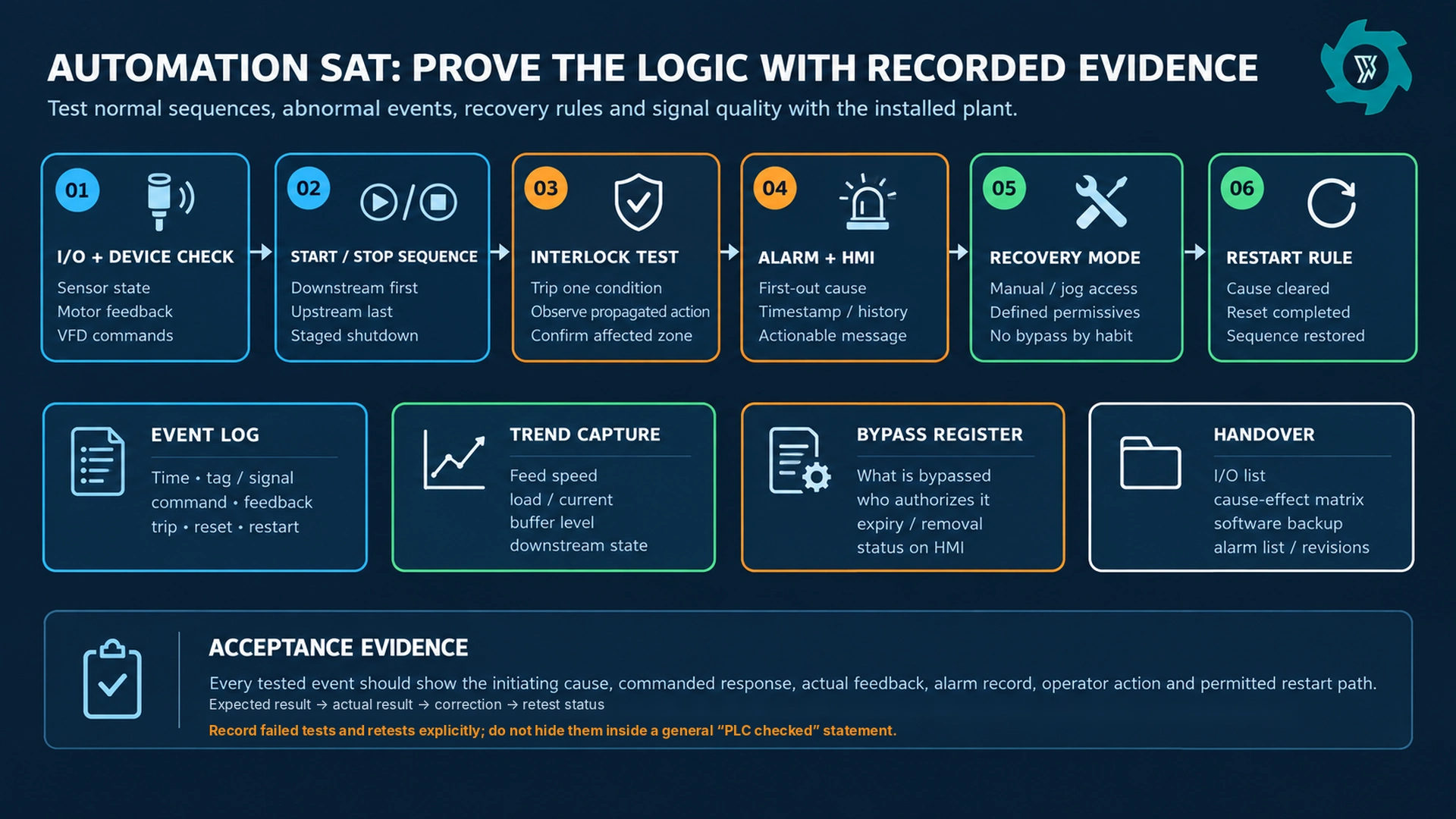
Trend capture is particularly useful for feed-control tests. Record feed speed, shredder load, buffer level, downstream state, reversals and trips on the same clock. The trend should show whether the controller reduced feed before the trip threshold, how quickly the buffer recovered, and whether the line returned smoothly to the normal band.
Keep a Bypass Register and Make Temporary Logic Visible
Commissioning often creates temporary bypasses: a missing level switch is simulated, an owner interface is forced ready, or an alarm is disabled while a device is replaced. The risk is not the temporary change itself; the risk is forgetting that it exists after the plant starts production.
Use a bypass register with tag, reason, authorizer, date, expiry condition and closure status. The HMI should make active overrides visible. Software backups should be versioned so the final handover copy is the tested production version, not an earlier laptop file. If the PLC supports change logs or user roles, decide how they will be used before the plant is handed to operations.
What Buyers Should Put in the Automation Scope
A clear automation scope is specific enough to compare quotations but flexible enough for the supplier to engineer the final hardware. The following items deserve written answers:
- Control platform: PLC, HMI, remote I/O and network architecture, including owner interface requirements.
- Motor control: starter or VFD type by drive, speed-reference ownership, local/remote selection and feedback signals.
- Sequence: automatic start and stop order, clear-out logic where used, and restart behavior after normal trips and power restoration.
- Process interlocks: downstream-ready logic, buffer level response, overload response, motion monitoring and dust-system dependencies.
- Safety boundary: safety functions, devices, zones and validation responsibility defined separately from normal PLC logic.
- Operator interface: overview, mode selection, setpoints, alarm history, first-out indication and trend capability.
- Recovery modes: manual, jog or local operation, with written limits and visible bypass status.
- Documentation: electrical drawings, I/O list, cause-and-effect matrix, alarm list, sequence narrative, software backup and final revision record.
- Acceptance: I/O checks, sequence tests, selected fault-injection tests, trend records, punch-list closure and retest evidence.
For the overall machine list and process functions, use the OCC recycling equipment guide. The automation package should not repeat that equipment schedule. Its job is to state how the installed machines exchange status, control material release, respond to faults and return to production.
Commission the Logic Around the Hardest Normal Feed, Not an Empty Conveyor
Many control problems appear only when the plant contains material. A belt starts correctly when empty but cannot accelerate under a deep OCC bed. A buffer level changes slowly when loose sheets are used but jumps when an opened bale collapses. A shredder current signal looks smooth on small boxes and becomes highly variable on thick multiwall corrugated. The control system should therefore be tuned and witnessed with representative material, including difficult-but-normal feed that remains inside the agreed envelope.
The acceptance record should state the operating mode, active recipe, important setpoints, abnormal events and any temporary bypasses. It should also record whether the observed stop came from process logic, equipment protection or the safety system. That distinction makes later diagnostics much easier.
When the plant can demonstrate those behaviors consistently, automation has done its job. The value is not the PLC cabinet itself. It is a line that releases material only when the next stage is ready, reduces feed before predictable overloads, makes the first cause of a trip visible, and restarts by a defined path rather than by trial and error.
Define the Control Logic Before the Cabinet Is Built
Send your OCC feed form, process sequence, target rate, planned buffers, owner-supplied interfaces and preferred operating modes. YUXI can prepare an automation scope with PLC/HMI functions, feed-control logic, interlocks and acceptance points matched to the installed line.
OCC Recycling Plant Automation FAQ
What should a PLC control in an OCC recycling plant?
The PLC should coordinate the connected process: machine permissives, start and stop sequence, upstream and downstream process interlocks, variable-speed feed control, buffer levels, motor and motion feedback, alarms, operating modes and selected data trends. Safety-related functions should be defined and validated separately according to the project risk assessment and applicable requirements.
Should the upstream conveyor stop whenever a downstream machine trips?
The response should follow the cause-and-effect design. If a buffer can safely absorb material, the upstream section may be allowed to complete a defined transfer. If continued feeding would block a chute, overflow a buffer or overload the next stage, upstream feed should slow or stop before that happens.
Which signals are most useful for OCC feed control?
Useful signals commonly include buffer level, shredder load or motor current, conveyor motion or speed, downstream-ready status and repeated reversal or trip information. The best combination depends on the physical line. Feed speed should respond to sustained process conditions rather than every short transient.
What automation documents should a buyer request from the supplier?
Request an I/O list, electrical drawings, cause-and-effect matrix, start/stop and recovery sequence narrative, alarm list or alarm philosophy, HMI screen set, network or interface information, software backup, revision record and the final SAT results. Owner-supplied equipment interfaces should show signal direction, meaning and responsibility.
How should OCC automation be tested during SAT?
Check I/O and device feedback, prove the automatic start and stop sequence, trigger selected process interlocks and faults, confirm alarm messages and first-out indication, test recovery and restart rules, and capture trends for feed speed, load, levels and downstream status. Record the expected result, actual result, correction and retest for each failed point.
Engineering References
- OSHA. Paper Recycling — workplace hazards.
- IEC. IEC 60204-1:2016 — machine electrical equipment; AMD1:2021.
- ISO. ISO 12100:2010 — machinery risk assessment.
- ISO. ISO 13849-1:2023 — safety-related control systems.
- ISO. ISO 13850:2015 — emergency-stop design.
- OSHA. 29 CFR 1910.147 — hazardous energy control.
- OSHA. 29 CFR 1910.212 — machine guarding.